Distributor PLC Omron
OMRON (PLC) Programmable Logic Controllers, along with easy-to-use Support Software, are available to flexibly handle applications from small-scale equipment to entire production lines with Programmable Logic Controllers such as those in the CJ1, CS1 and other series. PLC Omron comes with different series starting from Compact PLC Series, Modular PLC Series, and Rack PLC Series. It is important that in purchasing PLC Omron, you have deep understanding about PLC Omron Programming. This deep understanding about PLC Omron Programming includes basic understanding about industrial automation, PLC basic knowledge (how it works), Configuring PLC Omron hardware, Connecting input and output of the PLC, PLC Programming, Controlling PLC relay output, and many more. Therefore, PLC Omron has a wide variety of usage and is an important component in Industrial automation.Klasifikasi Omron PLC
Omron PLC diklasifikasikan menjadi dua model, yaitu Model Kompak dan Model Modular. Klasifikasi ini dibuat berdasarkan bagian perangkat keras yang diintegrasikan. Omron PLC Kompak memiliki bagian Power Supply, unit I/O, dan unit CPU yang terintegrasi menjadi satu kesatuan. Sedangkan Omron PLC Modular modulnya dapat dikonfigurasi dan dipasang sesuai kebutuhan sistem. Selain klasifikasi model, Omron PLC memiliki klasifikasi berdasarkan ukuran, diantaranya Mikro, Medium, dan Rak.Spesifikasi Omron PLC
Sebagai distributor OMRON, kami jual Omron PLC dengan spesifikasi Omron PLC yang diperlukan dalam sistem otomasi industri. Berikut ini beberapa spesifikasi Omron PLC yang tersedia.| Model Produk | Maks. I/O | Kapasitas Program | Instruksi | Waktu Eksekusi | Internal Work (IR) | Timer/Counter | Data Memory |
|---|---|---|---|---|---|---|---|
| CJ-Series | 2560 pts | 120K Step | 400 | 0.02 μs | 8192 bit | 4096 T/4096 C | 256K |
| CS1-Series | 5120 pts | 250K Step | 400 | 0.01 μs | 8192 bit | 4096 T/4096 C | 448K |
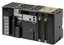
Omron PLC CJ2 SERIES
Categories: PLC OMRON, Industrial PLC Omron
Description
Innovation without growing pains
As a modern machine manufacturer you need to continuously increase the intelligence and flexibility of your product to remain competitive. But you also need to be absolutely certain that it all works perfectly, first time, every time.
The Omron PLC CJ2 SERIES is the result of years of experience as market leader in the field of modular controllers and represents a logical next step in controller design. It offers greater performance and faster I/O response as well as extreme scalability – so you will only need one family. In addition, programming, debugging and networking are faster and easier.
Welcome to the new CJ2 Family: built to give you innovation without growing pains.