| Model | S8AS-24006 | S8AS-24006N | S8AS-24006R | ||
|---|---|---|---|---|---|
| Efficiency (Typ.) | 80% min. | ||||
| Input condi- tions | Voltage range *1 | 100 to 240 VAC (85 to 264 VAC) | |||
| Frequency *1 | 50/60 Hz (47 to 63 Hz) | ||||
| Current | 100-V input | 3.8 A max. | |||
| 200-V input | 2.0 A max. | ||||
| Power factor *4 | 0.95 min. | ||||
| Harmonic current | EN61000-3-2 | ||||
| Leakage current | 100-V input | 0.5 mA max. | |||
| 200-V input | 1.0 mA max. | ||||
| Inrush current *2 | 100-V input | 25 A max. (for a cold start at 25°C) | |||
| 200-V input | 50 A max. (for a cold start at 25°C) | ||||
| Output condi- tions | Number of branches | 6 | |||
| Maximum cutoff output current (per branch) | 3.8 A | ||||
| Total output current | 10 A | ||||
| Allowable voltage range *3 | ±10% (with V.ADJ) | ||||
| Ripple noise voltage | 2.0% [P-P] max. (for rated input and output voltage) *4 | ||||
| Output leakage current | 10 mA max. | ||||
| Input fluctuation | 0.5% max. (Input: 85 to 264 VAC, 100% load) *5 | ||||
| Load fluctuation (rated input voltage) | 4.0% max. (rated input, 0% to 100% load) *5 | ||||
| Temperature fluctuation | 0.05%/°C max. | ||||
| Startup time *2 | 3,000 ms max. (for rated input and output voltage) *4 | ||||
| Output hold time *2 | 20 ms max. (for rated input and output voltage) *4 | ||||
| Func- tions | Tripping functions | Abnormal voltage tripping | 28.8 V (Cannot be changed.) | ||
| Abnormal current tripping *2 | Setting range: 0.5 to 3.8 A (in 0.1-A increments) | 3.8 A (Cannot be changed.) | Setting range: 0.5 to 3.8 A (in 0.1-A increments) | ||
| Abnormal total current tripping | Branch outputs are cut off when the total output current is more than 17 A for 2 s, 15 A for 5 s, 13 A for 10 s, or 12 A for 20 s. | ||||
| Tripping alarm output | Photoswitch output 30 VDC max. and 50 mA max., Leakage current: 0.1 mA max., Residual voltage: 2 V max. | ||||
| Undervoltage detection functions | Undervoltage detection | Setting range: 18.0 to 26.4 V (in 0.1-V increments) | 20.0 V (Cannot be changed.) | Setting range: 18.0 to 26.4 V (in 0.1-V increments) | |
| Undervoltage detection output | Photoswitch output 30 VDC max. and 50 mA max., Leakage current: 0.1 mA max., Residual voltage: 2 V max. | ||||
| Maintenance forecast monitor function | Maintenance forecast monitor | Setting range: 0.0 to 5.0 yr (in 0.5-yr increments) | 0.5 yr (Cannot be changed.) | Setting range: 0.0 to 5.0 yr (in 0.5-yr increments) | |
| Maintenance forecast monitor output | Photoswitch output 30 VDC max. and 50 mA max., Leakage current: 0.1 mA max., Residual voltage: 2 V max. | ||||
| Over- temperature detection function | Over- temperature | Setting range: 25 to 90°C (in 1°C increments) | 90°C (Cannot be changed.) | Setting range: 25 to 90°C | |
| Over- temperature output | Photoswitch output 30 VDC max. and 50 mA max., Leakage current: 0.1 mA max., Residual voltage: 2 V max. | ||||
| Display functions | Output voltage display | Display range:17.0 to 30.0 V Display accuracy: 2% rdg ±1 digit max. | |||
| Output current display | Branch output display range: 0.0 to 4.0 A Peak output current display range: 0.0 to 20.0 A Total current display range: 0.0 to 40.0 A Display accuracy: 5% FS (4 A) ±1 digit max. | ||||
| Maintenance forecast monitor display | Display range: FUL (Full)/HLF (Half)/0.0 to 5.0 yr | ||||
| Temperature display | Display range: -20 to 100°C Display accuracy: 2°C ±1 digit max. | ||||
| External Tripping Input | The input can be enabled or disabled for each branch output. 19.2 to 30.0 VDC, minimum signal width: 10 ms, tripping after input within 20 ms + the shutdown sequence set time | All branch outputs: Enabled (Cannot be changed.) 19.2 to 30.0 VDC, minimum signal width: 10 ms, tripping after input within 20 ms + the shutdown sequence set time | The input can be enabled or disabled for each branch output. 19.2 to 30.0 VDC, minimum signal width: 10 ms, tripping after input within 20 ms + the shutdown sequence set time | ||
| Startup sequence | Setting range: 0.0 to 99.9 s in 0.1-s increments | Branch output 1: 0.0 s (Cannot be changed.) Branch output 2: 0.4 s (Cannot be changed.) Branch output 3: 0.8 s (Cannot be changed.) Branch output 4: 1.2 s (Cannot be changed.) Branch output 5: 1.6 s (Cannot be changed.) Branch output 6: 2.0 s (Cannot be changed.) | Setting range: 0.0 to 99.9 s in 0.1-s increments | ||
| Shutdown sequence | Setting range: 0.0 to 99.9 s in 0.1-s increments | All branch outputs: 0.0 s (Cannot be changed.) | Setting range: 0.0 to 99.9 s in 0.1-s increments | ||
| Communications | Not supported | Supported (RS-485) | |||
| Sampling period | 1 ms | ||||
| Parallel connection | Not supported | ||||
| Series connection | Not supported | ||||
| Others | Ambient operating temperature | Refer to the derating curve (no icing or condensation). *2 | |||
| Storage temperature | -25 to 65°C | ||||
| Ambient operating humidity | 25% to 85% (storage: 25% to 90%) | ||||
| Withstand voltage | 3.0 kVAC for 1 min between all input terminals collectively and all branch output, all I/O signal, and all communications terminals collectively (Detection current: 20 mA) 2.0 kVAC for 1 min between all inputs and protective earth (Detection current: 20 mA) 1.0 kVAC for 1 min between protective earth and all branch output, all I/O signal, and all communications terminals collectively (Detection current: 20 mA) 500 VAC for 1 min between all branch output and all I/O signal/ communications terminals collectively (Detection current: 20 mA) 500 VAC for 1 min between all I/O signal terminals collectively and communications terminals collectively (Detection current: 20 mA) 500 VAC for 1 min between all I/O signal terminals collectively and all output signal terminals collectively (detection current: 20 mA) | ||||
| Insulation resistance | 100 MΩ min. at 500 VDC between the protective earth terminal or all input terminals collectively and all branch output, all I/O signal, and all communications terminals collectively | ||||
| Vibration resistance | No abnormality after 10 to 55 Hz at 0.375-mm single amplitude for 2 h each in 3 directions. | ||||
| Shock resistance | No abnormality after 150 m/s2 3 times each in 6 directions. | ||||
| Output indicator | Provided (Color: green) | ||||
| Conducted EMI | Conforms to EN 61204-3 Class A and FCC Class A. | ||||
| Radiated EMI | Conforms to EN 61204-3 Class A. | ||||
| Safety standards | cULus: UL508 (Listing. Class2: Per UL1310), CSA C22.2 No.107.1 (Class2: Per CSA C22.2 No.223) EN 62477-1 | ||||
| SEMI standard | SEMI F47-0706 (200 VAC input) | ||||
| Weight | 1,600 g max. | ||||
Distributor Power Supply Omron
OMRON provides many types of general-purpose Power Supplies, such as the type mounted to DIN rail or the type built into equipment. OMRON also provides the S8VS which provides notification of replacement timing, and the Buffer Block that handles momentary power interruptions, and other highly reliable Power Supplies.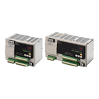
S8AS SERIES
Categories: Power Supply Omron
Description
• 240- and 480-W power supplies with and digital circuit protectors in a single package.
• Each branch output tripping current value can be easily set at 0.1-A increments.
• Startup and shutdown sequence control included.
• Various monitor displays and alarms (output voltage, output current, maintenance forecast monitor, temperature).
• Conforms to UL Class 2
• Mounts to DIN Rail.
For over 25 years, PT. Mitrainti Sejahtera Eletrindo (MISEL) has developed automation system solutions to assist our customers in achieving high efficiency and effectiveness in their manufacturing process. We become a trusted partner for local and global companies in diverse industries such as consumer products, tobacco industry, packaging companies, foods and beverages, pharmaceutical, industrial manufacturing, etc. With adequate experiences in automation industry, we are your first and best choice to support your automation needs.
Feel free to contact us for more information :
Sales & Marketing
Ruko Pengampon Square Blok D-31
Jl. Semut Baru, Kel. Bongkaran, Kec. Pabean Cantian Kota Surabaya – Jawa Timur
[email protected]
WhatsApp: +628170006907
T. (031) 355 1715
F. (031) 355 3995
Specifications
S8AS-24006[]
*1. Do not use an inverter output for the Power Supply. Inverters with an output frequency of 50/60 Hz are available, but
the rise in the internal temperature of the Power Supply may result in ignition or burning.
*2. Refer to Engineering Data on Data Sheet for details.
*3. If the output voltage adjuster (V. ADJ) is turned, the voltage will increase by more than 10% of the voltage adjustment
range. When adjusting the output voltage, confirm the actual output voltage from the Power Supply and be sure that
the load is not damaged. If the output voltage exceeds 28.8 V, all branch outputs will be cut off.
*4. Rated input and output conditions: Rated input voltage, rated frequency, rated output voltage, rated total output
current, and maximum cutoff output current.
*5. 100% load conditions: Rated output voltage, rated total output current, and maximum cutoff output current.
S8AS-48008[]
| Model | S8AS-48008 | S8AS-48008N | S8AS-48008R | ||
|---|---|---|---|---|---|
| Efficiency (Typ.) | 80% min. | ||||
| Input condi- tions | Voltage range *1 | 100 to 240 VAC (85 to 264 VAC) | |||
| Frequency *1 | 50/60 Hz (47 to 63 Hz) | ||||
| Current | 100-V input | 7.4 A max. | |||
| 200-V input | 3.9 A max. | ||||
| Power factor *4 | 0.95 min. | ||||
| Harmonic current | EN61000-3-2 | ||||
| Leakage current | 100-V input | 0.5 mA max. | |||
| 200-V input | 1.0 mA max. | ||||
| Inrush current *2 | 100-V input | 25 A max. (for a cold start at 25°C) | |||
| 200-V input | 50 A max. (for a cold start at 25°C) | ||||
| Output condi- tions | Number of branches | 8 | |||
| Maximum cutoff output current (per branch) | 3.8 A | ||||
| Total output current | 20 A | ||||
| Allowable voltage range *3 | ±10% (with V.ADJ) | ||||
| Ripple noise voltage | 2.0%[P-P] max. (for rated input and output voltage) *4 | ||||
| Output leakage current | 10 mA max. | ||||
| Input fluctuation | 0.5% max. (Input: 85 to 264 VAC, 100% load) *5 | ||||
| Load fluctuation (rated input voltage) | 4.0% max. (rated input, 0% to 100% load) *5 | ||||
| Temperature fluctuation | 0.05%/°C max. | ||||
| Startup time *2 | 3,000 ms max. (for rated input and output voltage) *4 | ||||
| Output hold time *2 | 20 ms min. (for rated input and output voltage) *4 | ||||
| Func- tions | Tripping functions | Abnormal voltage tripping | 28.8 V (Cannot be changed.) | ||
| Abnormal current tripping *2 | Setting range: 0.5 to 3.8 A (in 0.1-A increments) | 3.8 A (Cannot be changed.) | Setting range: 0.5 to 3.8 A (in 0.1-A increments) | ||
| Abnormal total current tripping | Branch outputs are cut off when the total output current is more than 27 A for 1 s, 25 A for 2 s, or 22.5 A for 5 s. | ||||
| Tripping alarm output | Photoswitch output 30 VDC max. and 50 mA max., Leakage current: 0.1 mA max., Residual voltage: 2 V max. | ||||
| Undervoltage detection functions | Undervoltage detection | Setting range: 18.0 to 26.4 V (in 0.1-V increments) | 20.0 V (Cannot be changed.) | Setting range: 18.0 to 26.4 V (in 0.1-V increments) | |
| Undervoltage detection output | Photoswitch output 30 VDC max. and 50 mA max., Leakage current: 0.1 mA max., Residual voltage: 2 V max. | ||||
| Maintenance forecast monitor function | Maintenance forecast monitor | Setting range: 0.0 to 5.0 yr (in 0.5-yr increments) | 0.5 yr (Cannot be changed.) | Setting range: 0.0 to 5.0 yr (in 0.5-yr increments) | |
| Maintenance forecast monitor output | Photoswitch output 30 VDC max. and 50 mA max., Leakage current: 0.1 mA max., Residual voltage: 2 V max. | ||||
| Over- temperature detection function | Over- temperature | Setting range: 25 to 90°C (in 1°C increments) | 90°C (Cannot be changed.) | Setting range: 25 to 90°C (in 1°C increments) | |
| Over- temperature output | Photoswitch output 30 VDC max. and 50 mA max., Leakage current: 0.1 mA max., Residual voltage: 2 V max. | ||||
| Display functions | Output voltage display | Display range:17.0 to 30.0 V Display accuracy: 2% rdg ±1 digit max. | |||
| Output current display | Branch output display range: 0.0 to 4.0 A Peak output current display range: 0.0 to 20.0 A Total current display range: 0.0 to 40.0 A Display accuracy: 5% FS (4 A) ±1 digit max. | ||||
| Maintenance forecast monitor display | Display range: FUL (Full)/HLF (Half)/0.0 to 5.0 yr | ||||
| Temperature display | Display range: -20 to 100°C Display accuracy: 2°C ±1 digit max. | ||||
| External Tripping Input | The input can be enabled or disabled for each branch output. 19.2 to 30 VDC, minimum signal width: 10 ms, tripping after input within 20 ms + the shutdown sequence set time | All branch outputs: Enabled (Cannot be changed.) 19.2 to 30 VDC, minimum signal width: 10 ms, tripping after input within 20 ms + the shutdown sequence set time | The input can be enabled or disabled for each branch output. 19.2 to 30 VDC, minimum signal width: 10 ms, tripping after input within 20 ms + the shutdown sequence set time | ||
| Startup sequence | Setting range: 0.0 to 99.9 s in 0.1-s increments | Branch output 1: 0.0 s (Cannot be changed.) Branch output 2: 0.4 s (Cannot be changed.) Branch output 3: 0.8 s (Cannot be changed.) Branch output 4: 1.2 s (Cannot be changed.) Branch output 5: 1.6 s (Cannot be changed.) Branch output 6: 2.0 s (Cannot be changed.) Branch output 7: 2.4 s (Cannot be changed.) Branch output 8: 2.8 s (Cannot be changed.) | Setting range: 0.0 to 99.9 s in 0.1-s increments | ||
| Shutdown sequence | Setting range: 0.0 to 99.9 s in 0.1-s increments | All branch outputs: 0.0 s (Cannot be changed.) | Setting range: 0.0 to 99.9 s in 0.1-s increments | ||
| Communications | Not supported | Supported (RS-485) | |||
| Sampling period | 1 ms | ||||
| Parallel connection | Not supported | ||||
| Series connection | Not supported | ||||
| Others | Ambient operating temperature | Refer to the derating curve (no icing or condensation). *2 | |||
| Storage temperature | -25 to 65°C | ||||
| Ambient operating humidity | 25% to 85% (storage: 25% to 90%) | ||||
| Withstand voltage | 3.0 kVAC for 1 min between all input terminals collectively and all branch output, all I/O signal, and all communications terminals collectively (Detection current: 20 mA) 2.0 kVAC for 1 min between all inputs and protective earth (Detection current: 20 mA) 1.0 kVAC for 1 min between protective earth and all branch output, all I/O signal, and all communications terminals collectively (Detection current: 30 mA) 500 VAC for 1 min between all branch output and all I/O signal/ communications terminals collectively (Detection current: 20 mA) 500 VAC for 1 min between all I/O signal terminals collectively and communications terminals collectively (Detection current: 20 mA) 500 VAC for 1 min between all I/O signal terminals collectively and all output signal terminals collectively (detection current: 20 mA) | ||||
| Insulation resistance | 100 MΩ min. at 500 VDC between the protective earth terminal or all input terminals collectively and all branch output, all I/O signal, and all communications terminals collectively | ||||
| Vibration resistance | No abnormality after 10 to 55 Hz at 0.375-mm single amplitude for 2 h each in 3 directions. | ||||
| Shock resistance | No abnormality after 150 m/s2 3 times each in 6 directions. | ||||
| Output indicator | Provided (Color: green) | ||||
| Conducted EMI | Conforms to EN 61204-3 Class A and FCC Class A. | ||||
| Radiated EMI | Conforms to EN 61204-3 Class A. | ||||
| Safety standards (pending) | cULus: UL508 (Listing. Class2: Per UL1310), CSA C22.2 No.107.1 (Class2: Per CSA C22.2 No.223) EN 62477-1 | ||||
| SEMI standard | SEMI F47-0706 (200 VAC input) | ||||
| Weight | 2,400 g max. | ||||
*1. Do not use an inverter output for the Power Supply. Inverters with an output frequency of 50/60 Hz are available, but
the rise in the internal temperature of the Power Supply may result in ignition or burning.
*2. Refer to Engineering Data on Data Sheet for details.
*3. If the output voltage adjuster (V. ADJ) is turned, the voltage will increase by more than 10% of the voltage adjustment
range. When adjusting the output voltage, confirm the actual output voltage from the Power Supply and be sure that
the load is not damaged. If the output voltage exceeds 28.8 V, all branch outputs will be cut off.
*4. Rated input and output conditions: Rated input voltage, rated frequency, rated output voltage, rated total output
current, and maximum cutoff output current.
*5. 100% load conditions: Rated output voltage, rated total output current, and maximum cutoff output current.