Distributor Inverter OMRON
OMRON Servo motors and inverters ideal for positioning, speed and torque controls in various business machine control fields. OMRON Inverters provide for energy-efficient operation of facilities and machines with fine speed control. The 3G3MX2 series has a direct connection to the NJ controller via EtherCAT.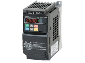
3G3MX2 SERIES
Categories: Inverter OMRON