Description
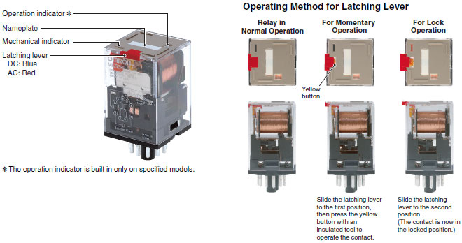
• Built-in mechanical indicator enables checking contact operation.
• Two modes can be used to check circuits for models with latching lever.
• Nameplate provided on models with latching lever.
• All materials are RoHS compliant.
• UL and IEC (TÜV) certification.

Example of Applications of Models with Latching Levers
Operation checks in relay sequence circuits
Specifications :
Coil Ratings
| Rated voltage | Rated current | Coil resistance |
Must operate voltage |
Must release voltage |
Max. voltage | Power consumption |
||
|---|---|---|---|---|---|---|---|---|
| 50 Hz | 60 Hz | |||||||
| AC | 6 V | 443 mA | 385 mA | 3.1 Ω | 80% max. of rated voltage |
30% min. of rated voltage at 60 Hz 25% min. of rated voltage at 50 Hz |
110% of rated voltage |
Approx. 2.3 VA at 60 Hz Approx. 2.7 VA at 50 Hz |
| 12 V | 221 mA | 193 mA | 13.7 Ω | |||||
| 24 V | 110 mA | 96.3 mA | 48.4 Ω | |||||
| 100 V | 26.6 mA | 23.1 mA | 760 Ω | |||||
| 110 V | 24.2 mA | 21.0 mA | 932 Ω | |||||
| 200 V | 13.3 mA | 11.6 mA | 3,160 Ω | |||||
| 220 V | 12.1 mA | 10.5 mA | 3,550 Ω | |||||
| 230 V | 10.0 mA | 11.5 mA | 4,250 Ω | |||||
| 240 V | 11.0 mA | 9.6 mA | 4,480 Ω | |||||
| DC | 6 V | 224 mA | 26.7 Ω | 15% min. of rated voltage |
Approx. 1.4 W | |||
| 12 V | 112 mA | 107 Ω | ||||||
| 24 V | 55.8 mA | 430 Ω | ||||||
| 48 V | 28.1 mA | 1,710 Ω | ||||||
| 100 V | 13.5 mA | 7,390 Ω | ||||||
| 110 V | 12.3 mA | 8,960 Ω | ||||||
| 125 V | 10.8 mA | 11,576 Ω | ||||||
for AC rated current and ±15% for DC coil resistance.
2. Performance characteristic data are measured at a coil temperature of 23°C.
3. The maximum voltage is one that is applicable instantaneously to the Relay coil at 23°C and not continuously.
4. For DC-operated Relays with the LED indicator built-in, add an LED current of approx. 5 mA to the rated current.
Contact Ratings
| Load | Resistive load (cosΦ = 1) | Inductive load (cosΦ = 0.4) | |
|---|---|---|---|
| Contact mechanism | Single | ||
| Contact material | AgSnIn | ||
| Rated load | NO | 10 A, 250 VAC 10A, 30 VDC |
7 A, 250 VAC |
| NC | 5 A, 250 VAC 5 A, 30 VDC |
||
| Rated carry current | 10 A | ||
| Max. switching voltage | 250 VAC, 250 VDC | ||
| Max. switching current | 10 A | ||
| Max. switching power | NO | 2,500 VA/300 W | |
| NC | 1,250 VA/150 W | ||
Characteristics
| Contact resistance | 100 mΩ max. |
|---|---|
| Operate time | AC: 20 ms max. DC: 30 ms max. |
| Release time | 20 ms max. (40 ms max. for built-in Diode Relays) |
| Max. operating frequency | Mechanical: 18,000 operations/h Electrical: 1,800 operations/h (under rated load) |
| Insulation resistance | 100 MΩ min. (at 500 VDC) |
| Dielectric strength | 2,500 VAC 50/60 Hz for 1 min between coil and contacts 1,000 VAC 50/60 Hz for 1 min between contacts of same polarity and terminals of the same polarity 2,500 VAC 50/60 Hz for 1 min between current-carrying parts, non-current-carrying parts, and opposite polarity |
| Insulation method | Basic insulation |
| Impulse withstand voltage | 4.5 kV between coil and contacts (with 1.2 × 50 μs impulse wave) 3.0 kV between contacts of different polarity (with 1.2 × 50 μs impulse wave) |
| Pollution degree | 3 |
| Rated insulation voltage | 250 V |
| Vibration resistance | Destruction: 10 to 55 to 10 Hz, 0.75-mm single amplitude (1.5-mm double amplitude) Malfunction: 10 to 55 to 10 Hz, 0.5-mm single amplitude (1.0-mm double amplitude) |
| Shock resistance | Destruction: 1,000 m/s2 (approx. 100 G) Malfunction: 100 m/s2 (approx. 10 G) |
| Endurance | Mechanical: 5,000,000 operations min. (at 18,000 operations/h under rated load) Electrical: 100,000 operations h. (at 1,800 operations/h under rated load) |
| Failure rate P level (reference value) |
10 mA at 1 VDC |
| Ambient temperature | Operating: -40 to 60°C (with no icing or condensation) |
| Ambient humidity | Operating: 5% to 85% |
| Weight | Approx. 90 g |
2. P level: λ60 = 0.1 × 10⁻⁶/operation
3. Ambient temperature of models with LED indicator is −25 to 60°C.
Approved Standards
UL508 (File No. E41515)

| Coil ratings | Contact ratings | Operations | |
|---|---|---|---|
| 6 to 110 VDC 6 to 240 VAC |
N.O. contact | 10 A, 250 V AC 50/60 Hz (Resistive) 10 A, 30 V DC (Resistive) 7 A, 250 V AC 50/60 Hz (General Use) |
100,000 |
| N.C. contact | 10 A, 250 V AC 50/60 Hz (Resistive) 10 A, 30 V DC (Resistive) 7 A, 250 V AC 50/60 Hz (General Use) |
100,000 | |
CSA Standard: CSA C22.2 No. 14 (File No. LR35535)

| Coil ratings | Number of Poles | Contact ratings | Operations |
|---|---|---|---|
| 6 to 125 VDC 6 to 240 VAC |
2 | 10 A, 250 V AC (Resistive) 10 A, 30 V DC (Resistive) 7 A, 250 V AC (General Use) |
100,000 |
| 3 | 10 A, 250 V AC (Resistive) Same Polarity 10 A, 30 V DC (Resistive) Same Polarity 7 A, 250 V AC (General Use) Same Polarity |
100,000 |
IEC Standard/TÜV Certification: IEC61810-1 (Certification No. R50104853)

| Coil ratings | Contact ratings | Operations | |
|---|---|---|---|
| 6, 12, 24, 48, 100, 110 VDC 6, 12, 24, 100, 110, 200, 220, 240 VAC |
N.O. contact | 10 A, 250 V AC 50/60 Hz (Resistive) 10 A, 30 V DC (Resistive) 7 A, 250 V AC 50/60 Hz (General Use) |
100,000 |
| N.C. contact | 5 A, 250 V AC 50/60 Hz (Resistive) 5 A, 30 V DC (Resistive) 7 A, 250 V AC 50/60 Hz (General Use) |
100,000 | |
Note: When Relays are mounted on the PF083A-E or PF113A-E, the maximum carrying current is 9 A.
For over 25 years, PT. Mitrainti Sejahtera Eletrindo (MISEL) has developed automation system solutions to assist our customers in achieving high efficiency and effectiveness in their manufacturing process. We become a trusted partner for local and global companies in diverse industries such as consumer products, tobacco industry, packaging companies, foods and beverages, pharmaceutical, industrial manufacturing, etc. With adequate experiences in automation industry, we are your first and best choice to support your automation needs.
Feel free to contact us for more information :
Sales & Marketing
Ruko Pengampon Square Blok D-31
Jl. Semut Baru, Kel. Bongkaran, Kec. Pabean Cantian Kota Surabaya – Jawa Timur
[email protected]
WhatsApp: +628170006907
T. (031) 355 1715
F. (031) 355 3995


Reviews
There are no reviews yet.